
610-459-9646
sales@sciotex.com
ENGINEERING GUIDE
What Is Process Control? A Guide to Industrial Process Control Systems
How industrial process control keeps temperature, pressure, flow, level and composition on target in chemical, pilot plant and production processes: control loops and PID, the hardware and software layers, PLC, DCS, SCADA and PC-based platforms, batch vs continuous control, and how to specify a system. Written by engineers who have built process control systems since 1997.
Last updated October 2026 · Written by Sciotex Engineering · 14 min read
DEFINITION
What is process control?
Process control is the continuous measurement and automatic adjustment of process variables, such as temperature, pressure, flow, level and composition, so that a chemical or industrial process stays at its setpoints, runs safely and makes consistent product.
An industrial process control system does this with sensors, controllers, final control elements such as valves and heaters, and software, arranged in feedback loops that run around the clock.
Process control is most closely tied to the process industries: chemicals, petrochemicals, refining, pharmaceuticals, food, metals, energy and materials, where product is made by flows, reactions and heat rather than by assembling parts. It applies equally to a bench-scale reactor, a pilot plant and a full production plant.
Process control vs process automation: process control is the regulating layer that holds variables on target. Process automation is the wider system around it: sequences and recipes, operator screens, alarms, data logging and links to plant business systems. A process control engineer designs both, but the control loops come first, because nothing else works if they are unstable.
HOW IT WORKS
How does a process control loop work?
Almost every process control system is built from feedback loops. Each loop watches one process variable (PV), compares it with the value you want, the setpoint (SP), and moves one manipulated variable to close the gap. A small reactor may have five loops; a production unit may have hundreds, plus the sequences and interlocks that coordinate them.
1. Measure
A sensor reads the process variable: a thermocouple or RTD for temperature, a transmitter for pressure, a flowmeter, a level probe or an analyzer.
2. Transmit
The reading travels to the controller as a standard signal, usually 4–20 mA, or as a digital value over a fieldbus or industrial Ethernet.
3. Compare
The controller subtracts the measured value from the setpoint. The difference is the error the loop is trying to remove.
4. Compute
A control algorithm, most often PID, turns the error and its history into a new output, typically 0–100% valve opening or heater power.
5. Act
The final control element moves, the process responds, and the loop repeats, from several times a second for flow to every second or two for temperature.
COMPONENTS
The components of a process control system
Sensors and transmitters
Thermocouples and RTDs for temperature, pressure and differential pressure transmitters, flowmeters, level instruments and online analyzers.
Measurement quality sets the limit on control quality: a loop cannot hold a variable tighter than it can measure it. See process control instrumentation.
Final control elements
Control valves, SCR-driven heaters, pumps and variable frequency drives, dosing pumps and mass flow controllers.
These do the physical work. A valve that is oversized, sticky or slow will defeat even a perfectly tuned controller.
Controllers
Single-loop panel controllers, PLCs and PACs, real-time PC-based controllers and DCS controllers run the control algorithms.
The choice depends on loop count, speed, sequencing complexity and how much flexibility the process needs.
Operator interface: HMI and SCADA
Screens that show the process, live trends, alarms, setpoint and recipe entry, and manual overrides.
Good HMI design lets an operator see in seconds whether the process is healthy and what needs attention.
Data logging and historian
Time-stamped records of every process variable, setpoint, alarm and operator action, plus batch and run reports.
In a pilot plant the data is often the main product: it is what process engineers use to scale up. See real-time process monitoring.
Interlocks, alarms and safety
Interlocks stop unsafe actions, alarms warn operators, and independent safety systems trip the process on high temperature or pressure.
Safety functions are engineered separately from the control loops, so a control fault cannot disable them.
These layers are the same whether the system controls a 2-liter bench reactor or a production unit; what changes is the number of loops, the speed required and how formally each layer is engineered and documented.
CONTROL STRATEGIES
Control strategies: on/off, PID, cascade, feedforward and ratio
Most loops use PID, but the strategy around the controller matters as much as the algorithm. These are the strategies a process control engineer reaches for most often.
| Strategy | How it works | Typical use | Limitation |
|---|---|---|---|
| On/off | Output fully on or off around the setpoint, with a deadband | Simple heaters, tank fill, non-critical temperatures | The variable always cycles above and below the setpoint |
| PID | Proportional, integral and derivative action correct the error continuously | Temperature, pressure, flow and level loops | Needs tuning; struggles with long dead time |
| Cascade | An outer loop sets the setpoint of a faster inner loop | Reactor temperature → jacket temperature; level → flow | Needs an extra measurement; inner loop must be much faster |
| Feedforward | Measures a disturbance and corrects before it upsets the process | Feed flow or feed temperature changes, ambient swings | Needs a model of the disturbance; used with feedback, not instead of it |
| Ratio | Holds one flow at a set ratio to another | Reactant feeds, blending, dilution | Only as good as both flow measurements |
| Sequence and recipe logic | Steps advance when conditions are met: charge, heat, hold, cool, discharge | Batch reactors, start-up and shutdown | Logic must cover every abnormal path, not just the normal one |
Swipe the table to see all columns →
Cascade and feedforward are where a well-engineered system pulls ahead of a basic one. A jacketed reactor under simple PID reacts only after its temperature has already moved; with a cascade on jacket temperature and feedforward from feed rate, it corrects before the batch sees the upset. See PID tuning for process loops for both.
Worked example: tuning a reactor temperature loop
Tuning starts with a step test: with the loop in manual, change the output once and record how the process responds. Three numbers describe most self-regulating loops: the process gain, the dead time and the time constant.
Worked example
1. Step test. The jacket valve output is stepped from 40% to 50%. Reactor temperature settles from 80.0 °C to 100.0 °C. Process gain K = 20 °C ÷ 10% = 2.0 °C per %. Nothing happens for the first 30 s, so dead time θ = 30 s. The temperature reaches 63% of its change (80 + 12.6 = 92.6 °C) 330 s after the step, so the time constant τ = 330 − 30 = 300 s.
2. Lambda tuning for a PI controller. Choose a closed-loop response time λ; setting λ = τ = 300 s gives a smooth, non-overshooting response. Controller gain Kc = τ ÷ (K × (λ + θ)) = 300 ÷ (2.0 × 330) = 0.45% per °C. Integral time Ti = τ = 300 s. A 2 °C error now produces an immediate output change of 0.45 × 2 = 0.9%, and the integral keeps adding until the error is gone.
3. Loop timing and difficulty. θ ÷ τ = 30 ÷ 300 = 0.1, an easy loop. Running the loop at least 10 times faster than its dead time means a scan of 3 s or less; 1 s is typical. A flow loop with a 2 s time constant needs a scan of around 100–200 ms, which is why fast loops run in the controller itself, not over a slow network.
Lambda tuning is one of several methods; it trades some speed for stability, which suits most chemical processes where overshoot is costly or unsafe. Always confirm the result with a small setpoint change before running product, and retune when the process changes, for example a different batch size or catalyst.
PLATFORMS
Types of process control systems: PLC, DCS, SCADA and PC-based
The controller platform is the biggest decision in a process control project. Each type below can run PID loops; they differ in scale, flexibility and how much engineering comes in the box. For a side-by-side view, see DCS vs PLC vs SCADA.
| Platform | What it is | Best for | Watch out for |
|---|---|---|---|
| Single-loop controllers | Panel controllers, each running one or a few PID loops with a local display | Skids, furnaces, small reactors, a handful of temperature loops | Limited sequencing, logging and coordination between loops |
| PLC with HMI | Programmable logic controller running logic and PID, with operator screens | Machine-like processes, skids, utilities, strong interlocking and sequencing | Advanced analysis, high-rate data and complex math are harder |
| DCS | Distributed control system: integrated controllers, I/O, HMI and historian from one platform | Large continuous plants with hundreds or thousands of loops | High cost and rigidity for small or frequently changing processes |
| SCADA | Supervisory software that monitors and commands PLCs or controllers across a site or many sites | Supervision, alarming and data collection, including remote sites | Supervisory layer only; the control loops run in the controllers below it |
| PC-based real-time | Industrial PC or real-time controller, for example NI CompactRIO with LabVIEW, with custom software | Pilot plants, R&D and specialized processes needing flexibility, high-speed data and custom algorithms | Needs disciplined software engineering and documentation to be maintainable |
| Hybrid | A PLC or safety system for interlocks, with a PC-based or SCADA layer for recipes, data and advanced control | Pilot and production plants that need both robustness and flexibility | Clear division of responsibilities between layers |
Swipe the table to see all columns →
In practice most systems are hybrids. A common pattern in chemical pilot plants is hard-wired or PLC-based safety interlocks, real-time controllers for the loops, and a supervisory application for recipes, trending and data. Our LabVIEW process control article covers when the PC-based layer is the right choice.
PROCESS TYPES
Batch, continuous and semi-batch process control
How a process runs changes what the control system has to do. Continuous processes are dominated by regulatory loops; batch processes add recipes, sequences and records.
Batch processes
A fixed quantity is charged, reacted or blended through defined steps, then discharged: reactors, fermenters, blending and coating.
Control is a recipe of phases (charge, heat, react, hold, cool), each with its own setpoints, and a record for every batch. The ISA-88 standard gives the structure; see batch control systems.
Continuous processes
Material flows in and product flows out without stopping: distillation, refining, continuous reactors and coating lines.
Control focuses on holding steady state through feed and ambient disturbances, so cascade, feedforward and ratio control matter most, along with safe start-up and shutdown sequences.
Semi-batch and pilot operation
Reactants are fed over time to a vessel, or a continuous unit is run in campaigns to study the process.
This is typical of pilot plants, where operating conditions change from run to run and the control system has to handle both regulatory loops and frequently edited sequences.
Many plants combine all three, for example continuous feed preparation feeding batch reactors, so the control system needs to support both regulatory control and recipe execution.
PILOT VS PRODUCTION
Pilot plant vs production plant control
A pilot plant control system and a production control system solve related but different problems. The pilot plant exists to learn; the production plant exists to repeat.
| Pilot plant | Production plant | |
|---|---|---|
| Purpose | Develop, prove and scale up the process | Make specified product at rate, every time |
| Recipes and setpoints | Change run to run; engineers edit them often | Locked and change-controlled |
| Instrumentation | Extra and higher-accuracy sensors, analyzers, sampling points | Only what is needed to control and protect |
| Data | High-rate logging of everything; data is a key output | Historian, batch records and KPIs |
| Control platform | Flexible: PC-based real-time, PLC plus custom supervisory software | Robust and standardized: DCS or PLC/SCADA |
| Change management | Fast iteration with engineering review | Formal validation, management of change |
| Safety | Same hazards at smaller scale; interlocks still independent | Full safety lifecycle and safety instrumented systems |
Swipe the table to see all columns →
Designing the pilot control system with scale-up in mind pays off: the same loop structure, tag names, sequences and data model can carry into the production design. See pilot plant control systems. Where a process mainly needs measurement and logging rather than closed-loop control, a data acquisition system may be the better starting point.
APPLICATIONS
Where industrial process control is used
Chemical reactors
Temperature, pressure, feed and agitation control for batch and continuous reactors, from bench scale to production.
Pilot plants and process development
Flexible control and high-rate data logging for process development, scale-up and tech transfer.
Thermal processing and metals
Furnaces, induction and IR heating, coating lines and controlled cooling run to recipe temperature profiles.
Electrochemical and plating
Bath temperature, current, timing and chemistry control for electroplating and deposition processes.
Powders and bulk solids
Feeder rate profiles, heater temperatures, weighing and material tracking.
Real-time process monitoring
Live trends, logging and alarms for plants and unattended sites, with alerts the moment values leave tolerance.
SELECTION
How to specify a process control system: a 10-point checklist
10-point process control specification checklist
- P&IDs: every loop, interlock and sequence identified
- I/O list: signal types, ranges and counts
- Loop speeds: required scan time for each loop type
- Recipes and sequences: steps, parameters and who may edit them
- Alarms and interlocks: limits, priorities and safe states
- Data: what to log, how fast and for how long
- Operator interface: screens, trends and user levels
- Integration: existing controllers, analyzers and plant systems
- Hazardous area and safety requirements
- Support: documentation, validation, spares and remote access
When packaged controllers are enough, and when to go custom
A few independent temperature loops on a skid are well served by panel controllers or a small PLC. Go custom when loops interact, when recipes and sequences change often, when data is as important as control, as in most pilot plants, or when the process needs algorithms or instrument integration that packaged systems cannot provide.
REAL-WORLD EXAMPLES
Process control systems we have built
These are pilot plant, production and laboratory process systems designed, programmed and supported by Sciotex engineers.
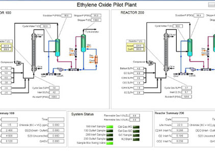
Ethylene oxide pilot plant
SCADA software for an ethylene oxide pilot plant, running on NI Compact FieldPoint real-time hardware.
View example →
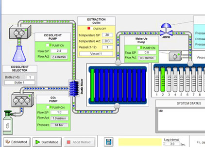
Reactor control systems
Numerous reactor systems built around Watlow and Eurotherm controllers for temperature, pressure and flow.
View example →
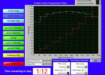
Powder feed control
Two feeders run independent feed-rate and heater-temperature profiles over serial links, with data logging.
View example →
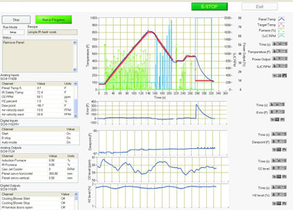
Hot dip simulator
PID heating and cooling plus 2-axis motion run recipe temperature profiles on a 1/10-scale steel coating line.
View example →
Scale-to-PLC signal converter
Polls six weigh scales over RS-232 and passes mass values to a Profibus-DP PLC network with low latency.
View example →
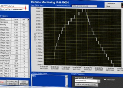
Remote facility monitoring
Logs environmental values at critical remote sites and raises alarms the moment they leave tolerance.
View example →
KEEP LEARNING
Process control articles
Pilot Plant Control Systems
How pilot plant control differs from production, and how to design one that scales.
Read article →
DCS vs PLC vs SCADA
What each platform does, where they overlap and which fits your process.
Read article →
PID Tuning for Process Loops
Tuning temperature, pressure and flow loops, plus cascade and feedforward control.
Read article →
Real-Time Process Monitoring
Trending, alarms and data historians for pilot and production plants.
Read article →
Batch Control Systems
Recipes, phases and ISA-88 for batch reactors and blending.
Read article →
Process Control Instrumentation
Sensors, transmitters, valves and 4–20 mA signals explained.
Read article →
LabVIEW for Process Control
When a LabVIEW and NI real-time system is the right control platform.
Read article →
Thermocouple Data Acquisition
Cold-junction compensation, accuracy and noise in temperature measurement.
Read article →
FAQ
Process control FAQs
What is process control in simple terms?
Process control is automatically measuring a process variable such as temperature, pressure or flow and adjusting a valve, heater or pump to keep it at the desired value, called the setpoint.
What is an example of process control?
A reactor temperature loop: a thermocouple measures the reactor temperature, a PID controller compares it with the setpoint and adjusts the valve that sends heating or cooling fluid through the reactor jacket.
What are the main types of process control?
By strategy: on/off, PID, cascade, feedforward and ratio control, plus sequence and recipe logic. By process: batch, continuous and semi-batch control. By platform: single-loop controllers, PLC, DCS, SCADA and PC-based real-time systems.
What is the difference between process control and process automation?
Process control is the regulating layer that holds variables on target. Process automation is the wider system: sequences and recipes, operator screens, alarms, data logging and integration with plant systems.
Should I use a PLC or a DCS for process control?
A DCS suits large continuous plants with many interacting loops and a long service life. A PLC, often with SCADA or a PC-based supervisory layer, suits skids, smaller plants, pilot plants and processes that change often.
What does a process control engineer do?
A process control engineer designs, programs, tunes and maintains control systems: selecting instruments and controllers, writing control logic and sequences, tuning loops, designing alarms and interlocks, and building the operator interface and data systems.
Can a pilot plant control system scale to production?
The platform often changes, but the design can scale: the loop structure, sequences, tag names, alarm philosophy and data model developed on the pilot plant can carry into the production system and shorten its commissioning.
How fast does a process control loop need to run?
A common rule of thumb is to run each loop at least 10 times faster than its dead time. Temperature loops often run every 0.5 to 2 seconds; flow and pressure loops typically need 100 to 250 milliseconds.
Need a process control system for your pilot or production plant?
Sciotex has designed, programmed and supported custom process control systems for chemical, pilot plant and production processes since 1997, from instruments and controllers to operator screens and data. Our 100% US-based team includes Certified LabVIEW Developers and Architects.

© Copyright 2026 by Coleman Technologies, Inc. DBA Sciotex