
610-459-9646
sales@sciotex.com
ENGINEERING GUIDE
What Is Automated Test Equipment (ATE)? The Complete Guide
How ATE systems stimulate, measure and judge a product without an operator in the loop: the architecture, test methods, fixtures, software, the numbers that size a test station, and how to choose one. Written by engineers who have built custom automated test systems since 1997.
Last updated October 2026 · Written by Sciotex Engineering · 17 min read
DEFINITION
What is automated test equipment (ATE)?
Automated test equipment (ATE) is a computer-controlled system that applies signals or power to a product, measures how it responds, compares each result with pass/fail limits and records the outcome, with little or no operator involvement.
An ATE system combines a controller running test software, measurement and stimulus instruments, signal switching, and a fixture or interface that connects to the unit under test (UUT).
Automatic test equipment and automated test equipment mean the same thing, and both are shortened to ATE. You will also see automated test system (ATS) and ATE test; in defense maintenance, an ATS is the ATE plus its test program sets and documentation. The product being tested is called the UUT, DUT (device under test) or EUT (equipment under test).
ATE ranges from a single fixture station that checks a sensor in 20 seconds to semiconductor testers with thousands of pins. Whatever the size, every ATE system answers four questions: what must be proven about the product, how accurately each parameter must be measured, how fast each unit must be tested, and what happens to the data.
HOW IT WORKS
How does an ATE system work?
Every automated test, from a relay check to a radar module, runs the same loop. The test executive steps through a sequence; each step sets up switching and instruments, takes a measurement and compares it with limits before moving on.
1. Load and connect
The operator, a robot or a conveyor places the UUT; the fixture closes, and the system reads its serial number by barcode, RFID or vision.
2. Stimulate
Power supplies, signal generators, loads and digital patterns put the UUT in a known state, just as it would be used in service.
3. Measure
DMMs, digitizers, counters and protocol interfaces capture voltage, current, timing, frequency, communication and sensor outputs.
4. Compare to limits
Each reading is checked against upper and lower limits, with guardbands for measurement uncertainty, to give a pass or fail per step.
5. Record and disposition
Results are stored against the serial number, pushed to MES or SPC, and the unit is passed, failed to a repair loop or binned.
COMPONENTS
The components of an automated test system
Controller and test executive
An industrial PC or PXI controller runs the test executive, the software that sequences steps, applies limits, handles retries and logs results.
It also manages operator login, product selection and the link to plant databases.
Measurement instruments
Digital multimeters, oscilloscopes and digitizers, DAQ cards, frequency counters, LCR meters, power analyzers and RF analyzers.
Instrument accuracy sets how tight your test limits can be (see the 4:1 rule below).
Stimulus, power and loads
Programmable DC supplies, source-measure units (SMUs), function and arbitrary waveform generators, electronic loads, and digital pattern generators.
High-power stimulus brings interlocks, fusing and safety covers into the design.
Switching and signal routing
Relay multiplexers and matrices let a handful of instruments reach hundreds of test points.
Relay type matters: reed relays for low-level signals, armature relays for current, and solid-state for speed; every relay adds resistance, thermal EMF and wear.
Interface: mass interconnect and fixtures
A mass interconnect gives every instrument a single, repeatable connection to an interchangeable fixture.
Fixtures use pogo pins (bed of nails), production connectors or cable harnesses. Contact life, alignment and changeover time drive fixture design; see our guide to test fixtures.
Handling, safety and environment
Manual drawers, pneumatic presses, conveyors or robots move the UUT. Light curtains, guarding and E-stops protect the operator.
Some tests add thermal chambers, vibration, pressure or vacuum to reproduce field conditions.
Many of these blocks are the same hardware found in a data acquisition system; what makes it ATE is the automated sequence, the limits and the pass/fail decision.
TEST METHODS
ATE test methods: ICT, functional, boundary scan and more
“ATE testing” covers several methods, and most products use two or three of them in sequence: structural tests find manufacturing defects early and cheaply, then functional and end-of-line tests prove the finished product works.
| Test method | What it checks | Access to the UUT | Strength | Limitation |
|---|---|---|---|---|
| In-circuit test (ICT) | Component values, shorts, opens, orientation on a bare or loaded PCB | Bed-of-nails fixture on test pads | Fast, pinpoints the faulty part | Fixture cost; does not prove the board works |
| Flying probe | Same faults as ICT | Moving probes, no fixture | No fixture, fast changeover | Slow per board; low volume |
| Boundary scan (JTAG, IEEE 1149.1) | Interconnects between digital devices, BGA joints | JTAG port only | Reaches pins you cannot probe | Only nets on JTAG-enabled parts |
| Functional test (FCT) | The assembly performs its function under power | Edge connectors, mass interconnect | Proves the product does its job | Less precise fault location |
| End-of-line (EOL) test | The finished product meets spec before shipping | Production connectors | Catches assembly and integration faults | Must fit the line takt time |
| Hardware-in-the-loop (HIL) | Controller behavior against a simulated machine or vehicle | Real-time simulator and I/O | Tests rare or unsafe conditions safely | Only as good as the model |
| Burn-in and ESS | Early-life failures under heat, voltage and cycling | Racks in chambers | Screens infant-mortality failures | Time, floor space and energy |
| Parametric / semiconductor test | Device parameters at wafer and package level | Probe cards, handlers | Very high volume and pin count | Very high capital cost |
Swipe the table to see all columns →
A common electronics flow is ICT or flying probe on the bare assembly (compare in-circuit vs functional test), boundary scan for dense digital parts, then functional test of the finished board and an end-of-line test of the complete product. The measurements most often automated in these steps are voltage and current, timing and frequency, digital and mixed-signal, temperature and RF.
Sizing an ATE station: three numbers that matter
Before choosing instruments, size the station. These three calculations decide how many stations you need, which instruments qualify and where your test limits sit.
Worked example
1. Throughput. Test time 45 s + load/unload 15 s = 60 s per unit, so one station tests 60 units per hour. Demand is 1,200 units a day over two 8-hour shifts = 1,200 ÷ 16 h = 75 units per hour. One station falls short (60 < 75): plan two stations, or cut the cycle to 48 s or less (3,600 ÷ 75 = 48).
2. Instrument accuracy (test uncertainty ratio). A 5.000 V rail with a ±50 mV tolerance, checked at the common 4:1 ratio, needs a measurement uncertainty of ±50 ÷ 4 = ±12.5 mV or better, including the meter, switching and wiring.
3. Guardbanding. To avoid passing bad parts, pull each limit in by that uncertainty: 4.950 + 0.0125 = 4.9625 V and 5.050 − 0.0125 = 5.0375 V. Units between 4.950 and 4.9625 V now fail; that small yield cost buys confidence that every shipped unit is in tolerance.
Then prove the measurement system itself with a gauge repeatability and reproducibility (GR&R) study: under 10% of tolerance is generally acceptable, 10–30% may be acceptable depending on the application, and over 30% means the station cannot reliably tell good units from bad.
ARCHITECTURES
Types of ATE systems
ATE is usually grouped by how the hardware is packaged. The right choice depends less on the technology than on volume, product mix and how long the system must stay in service.
| ATE architecture | How it is built | Best for | Watch out for |
|---|---|---|---|
| Rack-and-stack | Standalone bench instruments (GPIB, LAN/LXI, USB) in a 19-inch rack | Low volume, mixed products, R&D and design validation | Footprint, slower instrument communication |
| PXI / modular | Instrument modules in a PXI chassis with shared timing and triggers | High-mix production, synchronized multi-channel tests | Module ecosystem and driver dependence |
| Turnkey semiconductor ATE | High-pin-count tester with probers and handlers | Wafer and package test at very high volume | Capital cost, specialist programming |
| Application-specific (custom) | Purpose-built station around one product family: fixtures, sensors, motion, software | Production test of assemblies, sensors and electromechanical products | Needs a complete test specification up front |
| Hardware-in-the-loop rig | Real-time simulator, I/O and the controller under test | ECUs, battery management, motor and flight controllers | Model development and validation effort |
| Portable / depot ATE | Ruggedized, reconfigurable test sets with test program sets (TPS) | Military and aviation repair of line- and shop-replaceable units | Instrument obsolescence over long service lives |
Swipe the table to see all columns →
Most industrial test stations are hybrids: a PXI chassis for synchronized measurements, a few bench instruments for power or RF, and a custom fixture. See how this plays out in real ATE use cases in semiconductors, automotive and aerospace.
SOFTWARE
ATE software: test executive, code modules and data
Hardware takes the measurement; software decides what the system can do and how easy it is to live with. ATE software is usually built in three layers; our article on automated test software goes deeper.
Test executive (sequencer)
Runs the sequence, manages limits and retries, handles operator login and product variants, and generates reports.
Commercial executives such as NI TestStand or a purpose-built sequencer; the key is keeping limits and sequences in data, not hard-coded.
Code modules and drivers
The steps that talk to instruments and the UUT, written in LabVIEW, Python, C# or C++.
Instrument control relies on VISA, SCPI and IVI drivers, plus protocol stacks for CAN, LIN, Modbus, serial and Ethernet.
Data, traceability and reporting
Every result stored against a serial number, with station, fixture, software version and operator.
Feeds MES and SPC dashboards, so first-pass yield, Cpk and failure Pareto charts drive process fixes, not just pass/fail.
Good ATE software also includes a self-test or golden-unit check at start-up, calibration tracking for every instrument, and role-based access so production cannot change limits without engineering approval.
COMPARISONS
ATE vs manual test, DAQ, PLC and machine vision
These overlap, and many production lines use several together. The difference is the job each one is built to do.
| Primary job | Pass/fail decision | Speed and repeatability | Data output | |
|---|---|---|---|---|
| Automated test equipment | Prove each unit meets its specification | Automatic, per step | Seconds per unit, highly repeatable | Full record per serial number |
| Manual bench test | Engineer or technician checks a unit | Human judgment | Minutes per unit, operator-dependent | Paper or spreadsheet |
| Data acquisition (DAQ) system | Measure and record signals | Optional, usually offline | Continuous acquisition | Waveforms and trends |
| PLC | Control a machine or process | Simple interlocks | Fast, deterministic control | Limited measurement data |
| Machine vision | Inspect visible features and defects | Automatic, per image | Milliseconds per part | Images and measurements |
Swipe the table to see all columns →
A common pattern: a PLC runs the line, machine vision checks what can be seen, and ATE proves the electrical and functional performance that cannot. Data acquisition supplies the measurement layer inside many test stations.
APPLICATIONS
Where automated test equipment is used
Electronics and PCB assemblies
ICT, boundary scan and functional test of boards, power supplies, connectors and cable harnesses.
Semiconductors
Wafer probe, ASIC functional and parametric test, burn-in and final test at very high volume.
Automotive and EV
ECU, CAN bus, sensor and battery-module test, end-of-line checks and HIL validation.
Aerospace and defense
Avionics, radar modules, ring laser gyros and depot test of line-replaceable units.
Medical devices
Validated, fully traceable functional test supporting FDA 21 CFR Part 11 record requirements.
Industrial and energy
Relays, motors, gas analyzers, HVAC equipment in environmental chambers, and fiber optic production.
SELECTION
How to choose an ATE system: a 10-point checklist
10-point ATE specification checklist
- Test specification: every parameter, limit and test condition
- Throughput target in units per hour vs station cycle time
- Measurement uncertainty: at least 4:1 on critical limits
- Interface: connectors, pogo pins, mass interconnect, fixture life
- Product mix and changeover time between variants
- Stimulus, loads, power levels and safety interlocks
- Software: sequencer, operator screens, limit control, user roles
- Data: serial-number traceability, MES, database and SPC
- Calibration, self-test and maintainability
- Lifecycle: instrument obsolescence and spares for 10+ years
When off-the-shelf is enough, and when to go custom
Off-the-shelf testers and turnkey platforms work well for standard device types with established test methods, such as ICs on a semiconductor tester or bare boards on a flying prober.
Custom ATE pays off when the product is unique: unusual signals or sensors, mechanical motion, environmental conditions, legacy instruments to integrate, tight takt times, or a test specification that no catalog system covers. It also lets you own the software and the data format.
REAL-WORLD EXAMPLES
Automated test systems we have built
Theory is the easy part. These are production and laboratory test systems Sciotex has designed, programmed and supported.
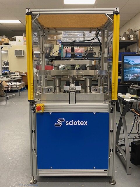
Ring laser gyro test
Over 60 high-speed digital and analog channels screen navigation-grade gyros.
View example →
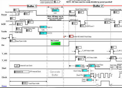
ASIC functional test
High-speed digital patterns in; timing and amplitude of outputs analyzed.
View example →
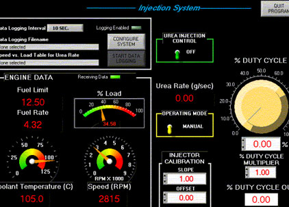
Automotive CAN bus tester
Logs data from a vehicle computer and drives test conditions from it.
View example →
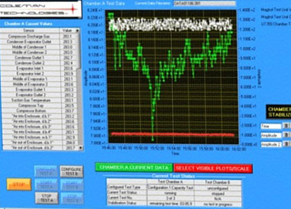
Environmental chamber test
Two chambers, 60+ thermocouples, GPIB instruments and recipe control.
View example →
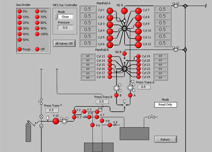
Automated gas tester
FTIR analysis of mixed-gas purity with database-driven test criteria.
View example →
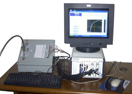
Cable test system
Automated continuity and electrical checks of cable assemblies.
View example →
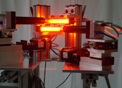
Fiber optic test
Microscopic defect detection on the draw tower during manufacturing.
View example →
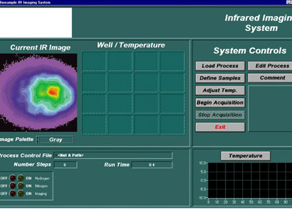
Biological sample IR analyzer
Automated infrared analysis of biological samples.
View example →
KEEP LEARNING
Automated test articles
End-of-Line Testing
What EOL tests check, how a station works and how to size it to takt time.
Read article →
Hardware-in-the-Loop (HIL) Testing
How HIL rigs test controllers against real-time plant models.
Read article →
Test Fixtures
Bed-of-nails, pogo pin and functional fixtures, spring probes and design for test.
Read article →
In-Circuit Test vs Functional Test
ICT, flying probe, boundary scan and FCT compared, with coverage examples.
Read article →
Automated Test Software
Test executives, TestStand, LabVIEW and Python, data and parallel testing.
Read article →
7 Measurements to Automate with an ATE System
Voltage, resistance, timing, digital, analog, temperature and RF done right.
Read article →
ATE Use Cases by Industry
Semiconductor, automotive, aerospace, medical and industrial test.
Read article →
LabVIEW for Test and Measurement
How LabVIEW is used to build instrument control and automated test software.
Read article →
FAQ
Automated test equipment FAQs
What is ATE in testing?
ATE stands for automated (or automatic) test equipment: a computer-controlled system that applies stimulus to a product, measures its response, compares results with limits and records pass or fail without an operator making the judgment.
Is there a difference between automatic and automated test equipment?
No. Automatic test equipment and automated test equipment are interchangeable names for the same thing, and both are abbreviated ATE. “Automated test system” is also used, and in defense programs an ATS means the ATE plus its test program sets and documentation.
What is the difference between ICT and functional test?
In-circuit test (ICT) probes individual components and nets on a board to find manufacturing defects such as shorts, opens and wrong values. Functional test powers the assembly and checks that it performs its intended job. ICT locates faults precisely; functional test proves the product works. Most production flows use both.
What software is used for automated test equipment?
Most ATE uses a test executive to sequence steps and manage limits and reports, such as NI TestStand or a custom sequencer, with code modules written in LabVIEW, Python, C# or C++. Instruments are controlled through VISA, SCPI and IVI drivers, and results go to a database, MES or SPC system.
What is a test program set (TPS)?
A test program set is the UUT-specific part of a test solution: the test program software, the interface device or fixture that connects the UUT to the ATE, and the documentation. The term is common in military and aerospace maintenance, where one ATE platform runs many TPSs.
What does an automated test system cost?
Cost depends on the number and type of measurements, instrument accuracy, fixture complexity, handling and automation, safety requirements, software features and the number of product variants. A clear test specification is the best way to get an accurate quote and avoid paying for capability you do not need.
How many test stations do I need?
Divide your required units per hour into 3,600 to get the maximum cycle time per station, then compare it with your test time plus load and unload time. For example, 75 units per hour allows 48 seconds per unit; a 60-second cycle needs two stations.
What does an ATE test engineer do?
An ATE test engineer turns a product specification into a test strategy, selects instruments and fixtures, writes and debugs test programs, sets limits and guardbands, validates the station with GR&R studies and supports production with yield analysis and troubleshooting.
Need an automated test system built around your product?
Sciotex has designed, programmed and supported custom ATE systems since 1997, from fixtures and instruments to test software and data. Our 100% US-based team includes Certified LabVIEW Developers and Architects.

© Copyright 2026 by Coleman Technologies, Inc. DBA Sciotex